
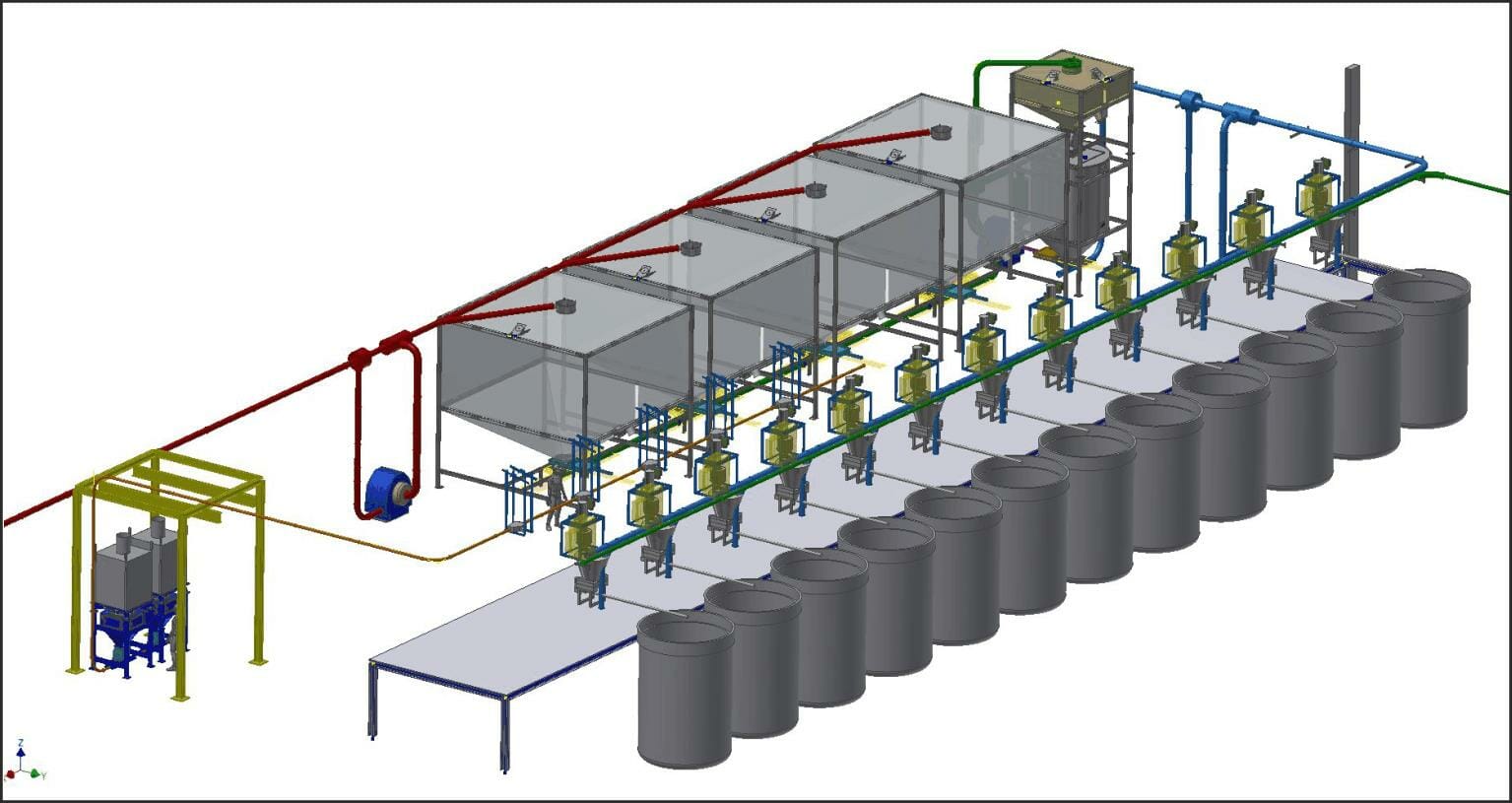
System Overview
CJ Waterhouse Company Limited were originally approached in summer 2017 by a worldwide manufacturing company to design, manufacture and implement a bespoke materials handling and automation solution for their new expanded polystyrene (EP) processing plant.
CJ Waterhouse were awarded the contract due to their extensive bespoke materials handling system solution experience and their previous works within the group.
The overall system takes in varying sizes of EP, creates a volumetric batch and transfers it to one of 12 blenders. Fibre materials are then introduced to the blender by weight together with liquid resins and additives. The finished product formed is a coated EP which is then conveyed to an out-loading system where weighed batches are created. The completed weighed batches are then used either in the downstream manufacturing process or sold on to third party manufactures for the production of industrial floatation devices for offshore applications.
The developed system essentially comprises of six component parts:
- EP intake
- EP measurement
- EP delivery
- Fibre delivery
- Finished product batching
- Control system
EP Intake
The EP intake system allows EP material of 5mm, 10mm and 40mm diameter to be delivered either by 2M3 tote bins or by bulk lorry. For lorry delivery the conveying system is directly coupled to the truck discharge chute and for tote bin deliveries an extraction lance is inserted into the container.
The EP material is transferred to four 65M3 bulk fabric silos via a Venturi conveying system providing negative pressure extraction at the infeed point and positive pressure conveying at the discharge point. A single conveying line is used which incorporates three diverter valves to provide automated routing to any of the four silos dependent upon material type and current level. The fabric silos incorporate a bespoke intake manifold and breathable upper surface to permit conveying air expulsion and material retention. Level monitoring within the silos is achieved using Ultrasonic sensors to provide an accurate measurement of the internal material volume together with upper and lower set points for filling and discharging purposes.
Silo discharging is via a bespoke slide valve and extraction chute assembly coupled to the downstream conveying line.

EP Measurement
Due to the very low and potentially fluctuating bulk density of the EP batches are measured by volume rather than by weight.
The EP measurement system again utilises a Venturi conveying system to extract material from the silo and deliver it to a fabric receiving hopper situated above the volumetric measurement hopper. The receiving hopper incorporates the same feed manifold and conveying air removal system as the bulk silos and is fitted with a rotary discharge valve to supply material to the volumetric hopper beneath. The rotary valve is utilised to ensure a controlled and constant feed rate of EP is achieved into the volumetric hopper to enhance volume accuracy.
The volumetric hopper is designed to produce a known volume batch of EP in accordance with the pre-specified recipe requirements. Upon receipt of the recipe information the rotary valve will begin to discharge material into the volumetric hopper. The material level within the hopper is continuously monitored using three ultrasonic sensors which take an average reading from 3 separate positions within the hopper to compensate for potential level fluctuations across the upper surface. This averaged level reading is used to calculate the material batch volume, upon reaching the required batch volume the rotary valve will stop and the batch is identified as complete and ready for transfer to the required tumbler destination.

EP Delivery
The EP delivery system transfers the pre-measured batch of material from the volumetric hopper to the required tumbler destination. This transfer is again completed using a Venturi conveying system via a single conveying pipe which incorporates eleven diverter valves to permit automated routing to any of the twelve tumblers.
Upon receipt of the transfer request and confirmation of interlock satisfaction the volumetric hopper discharge valve is opened, the conveying system blower is started and material is removed from the hopper under negative pressure. The EP material is conveyed directly into the tumbler through a dedicated connection spigot and conveying air is expelled through the tumbler vent assembly.
Fibre Delivery
The twelve tumblers are divided into two groups of six. The fibre delivery system to group one is of semi-automatic operation with material extracted from sacks whilst the delivery to group two is fully automated with extraction from bulk bags.
Each tumbler is equipped with the same fibre feed system which comprises of an agitated feed hopper and discharge screw to convey material into the tumbler. Above this feed hopper is a vacuum conveying hopper which is mounted upon a multi-point load cell weigh frame to provide accurate batch weighment of fibre materials.
With the semi-automated system the operator is required to manually insert the extraction lance into the fibre material sack. Material is then conveyed from the sack under vacuum to the weigh hopper, upon reaching the required target weight the vacuum conveying system stops and the weigher discharge valve opens therefore dropping the contents into the feed hopper beneath. If multiple fibre inclusions are required then the above process is repeated until all recipe requirements are fulfilled.
The automated fibre delivery system operates similarly to the manual system, however materials are conveyed to the vacuum weigh hoppers directly from one of two FIBC discharge stations. Both discharge stations incorporate drop through rotary valves to control the feed of material into a single conveying line. Five diverter valves are positioned within the conveying line to permit the automated routing of material to any of the six tumbler lines.
Finished Product Batching
The finished product (coated EP) is extracted from the tumbler and transferred to a storage hopper using a Venturi conveying system as with the uncoated EP systems. The storage hopper is fitted with a bespoke air separator unit which is designed to reduce the product velocity and remove surplus conveying air. From the storage hopper the finished product is discharged into a weighed tote bin via a multi-position slide valve. The operator sets the required batch weight from the local HMI display panel before commencing the discharge sequence, upon arrival at the target weight the discharge valve closes. The tote bin is then removed and replace with an empty one before the next batch discharge commences.

Control System
The control philosophy for the EPS and fibre handling system comprises of a central automation panel housing the main PLC and HMI display with a number of distributed remote I/O and operator display panels.
The central master HMI and remote HMI display screens provide the operators with both a graphical representation of the physical plant arrangement and specific data relating to the current system status together with operation prompting and alarm monitoring.
Automated control setup and manual operation of certain functions is also provided via data entry and push button functionality.
In addition to the above engineering & diagnosis functionality is provides via a number of password protected engineering pages.

Central Automation Panel
The central automation panel houses the main Siemens S7 PLC which provides automated control of the EP intake, measurement and delivery system. This panel also incorporates the master HMI screen providing graphical and data information, system controls, alarm monitoring and configuration for the entire materials handling system.

Intake display panel
The intake panel is located adjacent to the EP unloading area and incorporates a HMI unit providing specific information relating to the EP intake system. This display provides system information, controls, alarm monitoring, configuration and allows the operator to set the delivery type, intake material, silo destination and conveying parameters.

Fibre conveying panels 1 – 12
Each fibre weigher incorporates a locally mounted control panel housing a remote I/O module together with motor starters & variable speed drive for the associated feeder station. These panels provide automated control of the fibre conveying, weighing and feeding to the blender.

Outloading panel
The out-loading panel is located adjacent to the finished product weighing system and incorporates a remote I/O module providing automated control of the finished product conveying, storage and weighing system. This panel also incorporates a HMI display providing operator information for the tote bin filling and weighing system.

Network hub panel
All communication between plant control panels is provided via an Ethernet network. The Network panel provides a central connection hub for the Ethernet network.

For more information on the products, services and solutions offered by C J Waterhouse Company Limited please:
visit us at www.cjwaterhouse.co.uk
email us at [email protected] or call us on +44 (0) 1636 610792


")