The Type B earth leakage relay is an essential part for earth fault protection equipment on an installation where several switch mode power supplies are fed from the AC supply. The nature of a switch mode power supply is such that it may lead to high frequency, Harmonic interference and DC leakage currents elements on the AC network which will not be detected by an AC Type A or Type F earth leakage relay. This may leave to a risk of fire, damage to the installation or harm to operators.
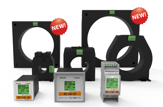
Frer’s X…DB3 series earth leakage relays Type B are designed to measure the DC, AC and high frequency leakage current. The continuous display of the system parameters, leakage current, alarm status, frequency and harmonic level on the LCD display makes it is possible to continuously monitor the insulation state and to program the preventive maintenance in order to help avoid unexpected power breaks.
Main functions:
– Continuous digital indication of the leakage current: total RMS, AC fundamental, AC high frequency
– Double threshold: total RMS and DC component
– Storing of the TRIP current values
– Internal clock and storage of the last 10 events
– RS485 Modbus RTU, measurements, event archive, scope
– Selectable anti Fibrillation filter with fire protection 300mA
– AC measurements up to 10kHz
– Automatic retry
– Logic Selectivity
– Selectable 3rd harmonic filter
The FRER type B earth leakage relays (series X … DB3), designed to intuitively and automatically detect leakage currents, allow the isolation status to be displayed continuously through the multi-color display.
Just one sensor (TDB series …) connected on the network is required to measure AC and DC networks, with a DC- 10kHz band, and a resolution up to 1mA. They have an integrated “demagnetisation” function with zero offset of the DC, which is automatically activated each time the sensor is switched on or when the relay is commanded which effectively clears the measurement error due to factors such as:
– presence of magnetic fields in DC (terrestrial magnetic field, permanent magnets, DC coils, …);
– temperature drifts;
– mechanical shocks or vibrations.
The measurement error of the RMS current (AC + DC) is proportional to the line current and depends on the arrangement of the cables passing through the sensor and on the distance of the adjacent cables.
The settings of low threshold currents will be possible only by centering the cables and controlled climatic conditions (temperature, vibrations, EMI).
MEASURE:
In MEASURING mode, the backlight of the display is GREEN. The first line shows the total True RMS value of the Differential Current and the annunciators related to the current settings.
On the second line it is possible to scroll the measurements relating to the continuous components of the measured values such as the network frequency and to the high frequency.
ALARM
In ALARM mode the backlight of the display is ORANGE and the alarm annunciator flashes.
If the differential current drops below the alarm threshold for the set release delay time, the device automatically returns to the measurement mode; if instead the Memory function is set, it is necessary to press the RESET key, the possible Test / Reset Remote input or the specific RESET Modbus RTU command. The pages and views are identical to the Measure mode.
TRIP
In the TRIP mode the display backlight is RED.
In the case of TRIP FOR DIFFERENTIAL CURRENT the TRMS value of the Differential Current which caused the trip is displayed on the first line while on the second line it is possible to scroll the measures related to the trip instant. The graphic bar is fixed at 100% and the Trip annunciator is on.
In the case of TEST OR TOROID INTERFACE FAILURE, the trip cause is displayed on the first line. The graphic bar is fixed
at 0% and only the Trip annunciator is on.
In trip mode the Differential Current should be canceled due to the opening of the System Release. If the relay continues to measure a non-zero differential current, the display backlighting becomes RED BLINKING to highlight the possible event.
Relay main functions:
– Continuous digital indication of leakage current: RMS total, DC, fundamental AC, high frequency AC.
– Double threshold, total RMS and DC component only
– Measurements in AC up to 10kHz.
– Internal clock with storage of the last 10 events
– Current TRIP level storage
– RS485 Modbus RTU, Measurements, event archive, oscilloscope
– 3rd harmonic filter and anti-fibrillation frequency filter with selectable 300mA fire
Anti-fibrillation
The anti-fibrillation is found in Type F and Type B earth leakage relays. It is a requirement of several norms, IEC 62423, VDE 0664-T-100, to which the Frer Type B and F relays are compliant. When a leakage current above the trip level, say greater than 30mA or 300mA is operating at a High frequency the conventional Type A earth leakage relay will not see the leakage current, so there is a threat of fire. The Anti Fibrillation filter sees the high Frequency and the current and will trip the Type B relay to reduce the risk of fire, damage to pant and machniery and the risk to life.
For further information, please contact [email protected] Tel: 01206 575755 or https://tvri.co.uk/frer-xdb3-type%20B-earth-leakage-relays.html