~ A deep dive into custom drive design ~
When working with a small space envelope or unique application, there may be times where standard, off-the-shelf motors, gearboxes and actuators aren’t quite the right fit. In such cases, a custom drive system may be the best alternative. Here, Stewart Goulding, managing director of actuation system specialist EMS, provides an insight into the custom actuator design and manufacturing process.
With applications ranging from robotics and surgical tools to disability aids and building automation, motors are a necessary component whenever there’s a need for electro-mechanical power. When used in conjunction with a gearbox, higher torques are achievable and speed can be reduced to usable levels depending on the needs of the application.
However, standard gearboxes may be too large for customers who are working within a reduced space envelope or when dealing with strict shape and size limitations. In these situations, it may be worth opting for a custom actuation design.
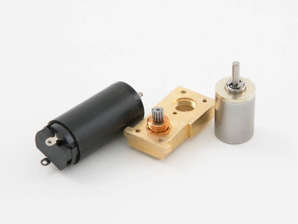
A custom drive system may involve altering the output configuration away from a typical inline construction by way of a transfer gearbox that allows the motor and gearbox to lay side-by-side, thereby halving the package length of the drive system. Other configurations such as bespoke worm wheel construction and making use of lesser-known plastics for gear materials to improve efficiency and reduce noise are just some of the ways to optimise performance — all of which are considerations EMS makes during the design process.
With an extensive portfolio of motor and gearbox options, working with a supplier that has the additional focus on custom design, such as EMS, means that the in-house expertise is there to provide a consultative and supportive experience to the customer. Demand is so high that EMS recently moved to larger premises to allow for further expansion and investment in machine tools, automation and a new CNC gear cutting machine, all used in the manufacturing process of custom drive systems.
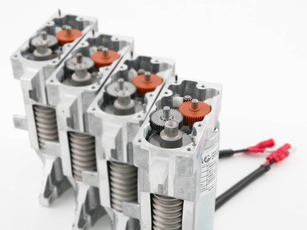
Starting with a specification
A collaborative approach between design engineers is key when creating a custom drive system and the customer and manufacturer will together outline the specification that the final product needs to meet.
These criteria include — but are not limited to — the desired speed and torque, duty cycle and the environment in which the drive system will need to operate. Limitations such as the customer’s power supply, current draw and space available will also need to be considered. It’s not always necessary to know all aspects of the requirements at the outset but these can be developed through the highly consultative approach, enabling a specification to be agreed in advance.
Once the specification has been agreed upon, design work can begin. A concept is formulated applying motor theory knowledge, background material strength calculations and 3D modelling software. Where necessary 3D printed prototype parts can be provided as the next step, giving an ideal opportunity to provide simple visualisation of the final design and to check size and fit into a customer’s existing space envelope.
Sharing of the CAD data from both sides is encouraged so that verifying the fit and integration can be done easily and any issues quickly identified in advance of cutting metal. Each design is by nature unique to that customer, thereby granting the customer a competitive edge in the market.
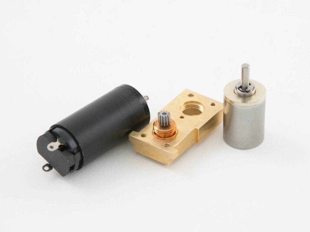
Right from the initial concept design, EMS considers Design for Manufacture. DFM allows for the simplification and refining of the product design to ensure that each element can be manufactured in-house, efficiently and cost effectively on EMS’s suite of machine tools. This may be with automation, or, if volume permits, higher volume processes. Die casting in aluminium or zinc may be considered, particularly for the enclosure.
The manufacture of spur, helical and worm gears is done using dedicated gear cutting machines or driven tool CNC lathes and the addition of CNC gear cutting further enhances capability. High precision, complex shapes can be achieved in a single operation, increasing productivity and ensuring high mechanical integrity of the component.
Prototypes are manufactured using intended production methods and supplied to the customer for full validation and life testing in the final application. Accredited to 9001:2015 quality, longevity and reliability is designed into each drive system. Supported by a comprehensive quality department equipped with the latest inspection equipment, a First Article Inspection (FAI) report is provided with each new prototype, providing detailed verification and comparison of the product design to the eventual manufactured part.
Following product approval and the start of production, the relationship formed between the customer and the manufacturer remains strong through the life cycle of the product; investing in a custom drive system is also about investing in a long-term partnership that will last the life of the product, and beyond.
Developing a custom drive system doesn’t have to be an overcomplicated process. By taking a collaborative approach, customers can feel reassured that the manufacturer has the needs of their product at the core of the design, as well as the expertise to deliver a quality drive system.

