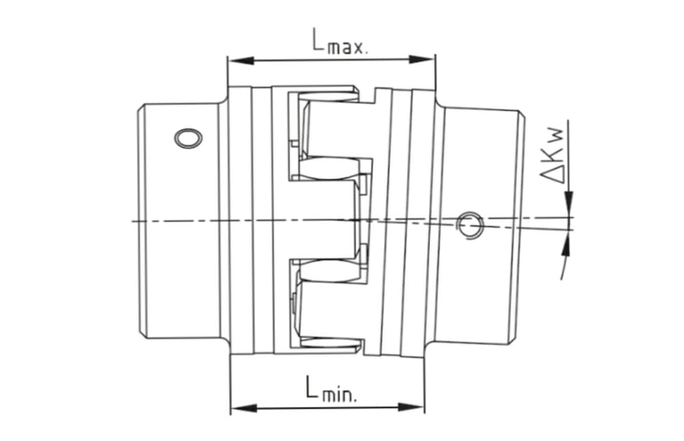
A basic introduction to misalignment in flexible couplings.
Let’s say you want to power a pump; this means at the very least you will need a pump, a motor, and a means of transmitting rotational power. Generally speaking, the power from the motor will rotate the shaft, which transmits power through the coupling to the pump. Sounds pretty basic right? Unfortunately, in many instances, massive amounts of power must be transmitted at challenging angles, which can cause significant damage to the system. Correct shaft alignment not only increases output (by reducing downtime for repairs), but it also reduces power consumption and improves the overall efficiency of the pump.
Shaft misalignment exists when two shafts joined by a coupling are unevenly aligned. Although flexible couplings are designed to withstand some movement and vibration, they have limits that should not be exceeded. In order to combat the fact that nearly 50% of damage to rotating equipment is caused by misalignment, manufacturers test and publish maximum misalignment figures as a guide for the proper functioning of a system. However, these numbers are not as straightforward as they seem. Some manufacturers publish maximum torque ratings based on perfect alignment of a system, while other manufacturers will be more conservative and publish maximum performance figures based on maximum misalignment scenarios.
Generally speaking, the misalignment figures published by manufacturers are the maximum allowances that a coupling can cope with, period. However, these numbers typically do not take into account various environmental or operating conditions such as temperature, exposure to chemicals, and the run cycle (i.e.: whether the coupling will have to withstand continuous stops and starts). In addition to these conditions, simultaneous misalignment combinations must be considered as well. For instance, a coupling is not able to withstand operating at the maximum tolerance for both excessive angular offset and misalignment simultaneously.
Most commonly, misalignment occurs when the degree of misalignment is underestimated, which forces the coupling (and in the case of jaw couplings, a flexible spider element) to deal with loads that exceed specifications. This causes excess vibration and friction which can lead to premature wear to the system, excessive energy consumption, and production downtime. Prolonged misalignment can also damage bearings, seals, and cause shaft and/or coupling failure.
Types of Misalignment
It’s important to note that shaft misalignment can be caused by a number of alignment issues. The most common forms of misalignment are axial, radial (a.k.a. parallel or offset), and angular, as seen in the jaw coupling misalignment images above.
Axial misalignment happens when coupling components are assembled either to close to each other or too far apart. This results in an inefficient transmission of power. If too far apart then engagement between driving and driven components will be less than required and can result in excessive points of wear, likely resulting in the damage of the spider element of a jaw coupling. If assembled too closely, the flexibility of the coupling may be restricted and similar points of wear will likely occur.
Radial misalignment occurs when two shafts are positioned at parallel to each other, but with different centerlines. This type of misalignment can be seen where one shaft is positioned higher than the other.
In contrast, angular or gap misalignment exists when two shafts are situated at different angles (not parallel) to one another. Sometimes, both parallel and angular misalignment exist. In these circumstances, there must be two points where the coupling can flex in order to accommodate both misalignments.
When jaw-type couplings are forced to cope with misalignment beyond the allowable misalignment, there will be visible damage to the coupling. Such damage will result in a significantly depleted lifespan. Unfortunately, simply replacing the coupling and subsequent spider element will not rectify the issue. The best solution is to realign the system. However, since this requires downtime for repairs, it is not always an option. Therefore, it may also be acceptable to replace the damaged coupling with a different design that is better equipped to handle the required misalignment.
Operating within misalignment allowances ensures that couplings have a significantly longer lifespan, which reduces system downtime, and ultimately saves you money. However, even with ‘perfect’ applications, some issues such as misalignment may still arise, which is why continual monitoring and maintenance is equally as important as the initial selection and assembly process.
Keep an eye out for future blogs where we will be tackling the misalignment types individually, looking for some of the telltale signs can help identify which type of misalignment is occurring.

 August 16, 2018Comments Off on The Fundamentals of Coupling Misalignment


