Cloud and cyber security in critical energy applications – Digitalization and IoT (Internet of Things) is a clear trend within power plants and substations, just as it is in industrial automation. The Smart Grid is certainly a driving factor, but there are also other reasons for this change. Operators often find that only having data available in the control room is insufficient. Instead, they want to monitor transformers remotely, implement new maintenance concepts from anywhere, optimize utilization and commissioning, or retrieve environmental data online. This requires a solution with a high level of cybersecurity that guarantee critical control data to be strictly separated from monitoring data. The solution should also be easy to use and have a compact form factor to ensure that it is suitable for retrofitting and that it fits into existing cabinets.
Cybersecurity of utmost importance
Substations which convert high transmission voltage into consumer voltage are an important part of the electrical grid, not only for municipalities but also for the railways and industrial companies to name but a few. They usually consist of power transformers, switchgear and a lot of equipment for measurement and control. Substations are usually managed from a control room, or remotely from control centres. This control path is subject to strict security regulations as a successful hacker attack could have catastrophic consequences. There is also a need for cloud-based monitoring. But how can this be achieved without neglecting the required cybersecurity?
Two separate data streams
In principle, there are two different data streams in substations: the first is the control data with which the control room communicates with the substation or individual devices. Control data means sending commands such as “Turn switch on”, “Measure now” or “Send measured value”. This critical communication runs in real time according to the protocols used in the energy sector such as IEC61850 or IEC60870-5-104. The security requirements are high and unauthorized data must be excluded.
The second data stream delivers monitoring data from sensors and devices to the control room. Real-time communication is not required here but the data packages are usually more extensive for this IoT data. Of course, the data must not be compromised here either, which is why communication is usually handled via TLS or VPN, for example.
There are also event-based alarm notifications that can be transmitted via independent data channels such as MQTT or SMS. Since the data only flows one way towards the control room or the cloud, this data stream and the transmitting device are well protected against attacks.
Typical data that is monitored
The data typically transmitted along the monitoring path includes, for instance, temperatures of transformers, high-voltage lines and motors, or oil pressure in transformers. If we take SF6-insulated circuit breakers as an example, it is possible to monitor gas pressure, temperature and gas humidity, and transformers, cables or battery back-up systems can provide voltage data. Data from building management can also be made available via the monitoring path. For example, door sensors of the access control system, air conditioning values or even a robot lawn mower can be monitored.
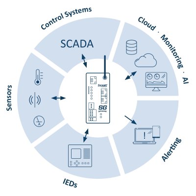
The data involved can come from various sources. Some data comes directly from the “heart” of the substation – values of the IEDs (Intelligent Electronic Devices), i.e. the control computer for the switchgear or measuring devices in the station. Other data is provided by additional sensors that are commonplace in the industrial environment or in building management.
How to gather and forward the data?
So how is it possible to gather the various data and how is it transmitted to ensure the required level of cybersecurity?
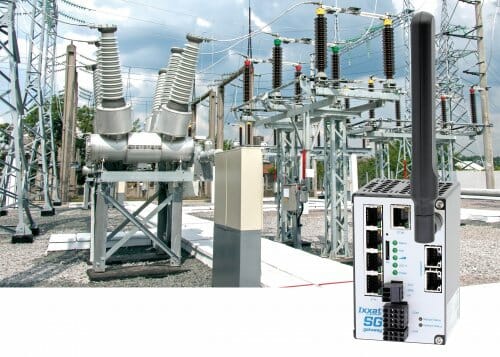
There are readily available gateways for this task (Fig. 1), such as the Ixxat SG gateway from HMS Networks. These gateways combine the functionality of RTUs (Remote Terminal Units), controllers and gateways; opening up possibilities to digitize substations and distribution networks. Existing systems, new devices and control systems can be connected quickly – regardless of the communication technology or manufacturer.
Here is an example to demonstrate how the monitoring works in practice:

A gateway collects the data from the various sources via the relevant ports.
Monitoring and added value
Protocol conversion and, where applicable, media disruption, mean that such a cloud connection is very secure. In addition, the data is only transmitted in one direction; access options are initially not provided but can be defined as exceptions if necessary. Configuration of these types of gateways is usually graphical and does not require any programming knowledge or additional software.
There are many use case scenarios. For example, a sensor manufacturer can use a Smart Grid gateway as a platform for communication with its private cloud, for remote monitoring, surveillance and maintenance planning. Substations can digitize the energy supply in an easy way: The gateway feeds the measured data – either from IEDs or sensors into the control system and can forward it directly to the cloud (MQTT) via an integrated LTE modem where it remains available for continual status monitoring.

The control unit of the UPS communicates with the gateway via Modbus and is connected to the control room via an IEC61850-based gateway. The status data of the individual battery cells is sent in parallel via MQTT to the manufacturer’s private cloud.

Author: Freddy Dahlberg, Business Development Manager Ixxat at HMS Networks
You can find more information on this topic at: www.ixxat.com/en/energy


