~ How to select the best type of impressed current cathodic protection system for your application ~
For larger mission-critical steel and concrete structures, such as bridges, ports, wharves, tanks or industrial pipelines, impressed current cathodic protection (ICCP) systems are often used to protect key assets from the ongoing threat of corrosion. The two main types of ICCP technology are phase control and switch mode and, while both have their strengths, each are better suited to different applications. Here David Celine, managing director of cathodic protection specialist Omniflex, explains how to choose the best system for the job.
There are two main technologies currently used to control the output voltage or current of transformer/rectifiers (T/Rs). The first is phase control technology, where AC power is passed through a large AC transformer and then rectified to produce a controlled DC output to the anodes. The second is switch-mode technology, where AC power is first rectified to high voltage DC power and then much smaller high frequency transformers and rectifiers are used to create controlled DC outputs. This technique allows smaller and more efficient outputs to be created that can be more easily controlled. While both technologies are hugely important to the global CP market, it is not always clear which is best to use for a specific project.
Phase control vs switch mode
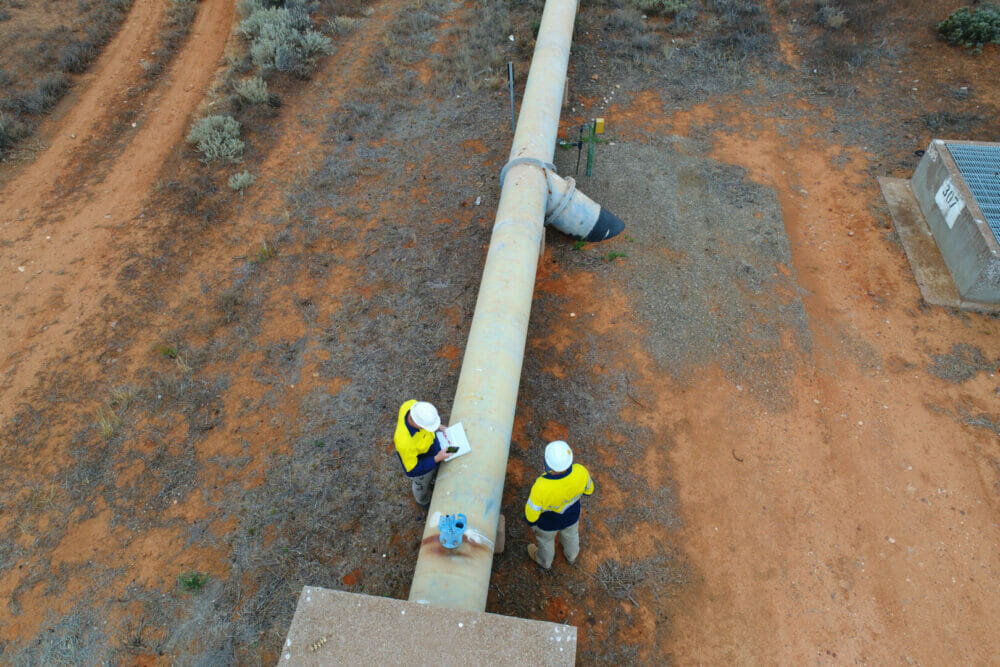
Phase control T/Rs are best used in larger ICCP systems with outputs greater than approximately 150 Amps and only one zone of protection to control. A good example of this is pipelines where one large T/R located at one end of the pipeline sends current along the pipeline to provide protection. This is a large market for CP systems globally, emphasizing the importance of phase control systems.
Because of the simplicity of the design, phase control CP technology is famously reliable, but is more difficult to control, especially when driving multiple anodes in parallel or when smaller currents are required.
Switch-mode technology is better suited to smaller currents driving more individual zones or protection, as found more often in concrete ICCP systems and distributed steel CP systems. A good example here is wharves, where multiple water anodes are distributed down the length of the wharf in individually controllable and monitorable zones. Smaller more compact switch-mode T/R modules also makes the technology well suited for use in distributed CP systems, where locating T/R’s closer to the anodes provides significant savings in installation costs, due to reduced cabling, and lower operating costs.

Switch-mode technology is also more suited for use in concrete applications, where the current outputs are lower, and more zones are required to achieve more uniform protection over the structure.
Switch-mode T/R’s are also more power efficient. For example, a typical phase control T/R will operate at approximately 75 per cent efficiency, meaning a quarter of your electricity bill is spent on wasted energy. Practically, this is often worse, as CP system designers will not specify a T/R to operate at 100 per cent load as it leaves no allowance for changing requirements. The large overhead power loss in the AC transformer becomes a larger percentage of the output power as the output reduces making the efficiency even worse. However, switch-mode technology generally operates at approximately 90 per cent efficiency across its full operating range, meaning wasted energy is cut by at least 15 per cent and electricity bills are drastically reduced.
Many CP system designers are yet to fully reap the benefits of switch-mode technology as they are still designing systems around a few large T/R outputs. This means that if the initial blueprint contains only one T/R, before the system’s objectives are outlined, then designers are slaves to phase control regardless of whether or not it is the best type of CP system for the job.
To avoid this, system designers should adopt an objective-oriented approach. This means, before T/R size and locations are selected, they should consider factors such as the number, current requirements and location of anodes to be installed and then optimising the design and location of the T/R’s to achieve lower installation and operating costs for the asset owner with reduced cabling and lower energy bills.
Omniflex is a global, industry-leading designer and manufacturer of CP and remote monitoring systems for both steel and concrete applications, whether they be galvanic, impressed current or hybrid systems. Omniflex offers both phase control T/Rs and switch-mode T/Rs, and can advise on the best technology for any given application.
To find out more, visit Omniflex’s website and download the company’s new cathodic protection industry overview.

